
LMH5401EVM
The LMH5401EVM is an evaluationmodule for the single LMH5401 amplifier in a 14-lead high performanceRFpackage. Thisevaluationmodule isdesigned toquicklyandeasilydemonstrate the functionalityandversatilityof theamplifier.TheEVMisreadytoconnect topower,signalsource,andtest instrumentsthroughtheuseofonboardconnectors.TheEVMcomesconfiguredforeasyconnectionwith common50-Ωlaboratoryequipmentonitsinputsandoutputs.Theamplifier isconfiguredforsingle-ended inputwithgainof12dB(4V/V).Theboardhasdifferentialoutputs,oneforeachof theamplifieroutputs. It canbeeasilyconfiguredfordifferential inputs,andsingle-orsplit-supplyoperation.
1 Features
• Configured for split-supply operation and easily modified for single supply
• Single ended or differential input signals
• Fully differential output
• Designed for easy connection to standard 50-Ω input/output impedance test equipment
• Inputs and outputs include SMA connectors
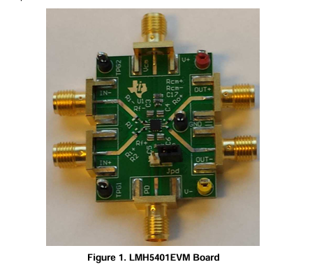
3 Power Connections
The LMH5401EVM is equipped with test loops for easy connection of power. The positive supply input is red and is labeled V+. The negative supply input is yellow and is labeled V–. Ground is black and is labeled GND.
3.1 Split-Supply Operation
To operate as split supply, apply the positive supply voltage to V+, negative supply voltage to V– , and the ground reference from supply to GND. The supply voltages do not need to be symmetrical, provided that the total supply voltage is between 3.15 V and 5.25 V, any combination of positive and negative supply voltages is acceptable. This feature is often used when the output common mode voltage must be set to a particular value. For best performance, the power supply voltages should be symmetrical around the desired output common-mode voltage.
3.2 Single-Supply Operation
To operate as single supply, connect jumper V– to GND, and apply the positive supply voltage to V+. Inputs and outputs must be biased as in the LMH5401 datasheet (SBOS710) specifications for proper operation.
4 Input and Output Connections
The LMH5401EVM is equipped with SMA connectors for easy connection of signal generators and analysis equipment. As shipped, the EVM is configured for a gain of 12 dB, split supply, single-ended input and differential outputs each with 50-Ω termination. For best results, signals must be routed to and from the EVM with cables having 50-Ω characteristic impedance. The input connectors for single-ended input signals are IN+ and IN– which are symmetrical. The output connectors are OUT+ and OUT–. In addition to the signal cables a 50-Ω resistive termination is required for the unused input. See the LMH5401 datasheet for additional detail on configuring the device.
4.1 CM(Output Common Mode Voltage) Input
The LMH5401 device has an output common-mode control pin that sets the output common mode voltage. The evaluation board is configured with a resistive divider to set the output common mode voltage at the mid supply voltage. If a different output common-mode voltage is specified, the SMA connector can be used to connect an external voltage source. The valid voltage range for the CM pin is approximately ([V+]– 2 V) to ([V–] + 2 V). See the LMH5401 datasheet for performance curves that show how performance is impacted by an output common mode voltage that is not at the mid-supply voltage.
4.2 PD(Power Down) Input
The LMH5401 device has a power-down input pin that allows the amplifier to enter a low-power state when it does not need to be active. The LMH5401 PD pin is referenced to the GND pin. The threshold voltage is 1.1 V. Any voltage over 1.2 V above the ground reference pins will disable the amplifier. Any input below 0.9 V enables the amplifier. Because the PD pin is not referenced to either of the supply pins the same logic level can be used for the PD function regardless of the configuration of the supply voltages. The LMH5401EVM has a jumper (JPD) that allows the amplifier to be manually disabled. In order to facilitate driving the PD pin with a high-speed signal source, the resistor-capacitor combination (Rsd/C9) provides high frequency termination for signals from a 50-Ω pulse generator.
4.3 Single-Ended Inputs
The LMH5401 device was designed for use with 50-Ω single-ended inputs. Even though the board was designed for single-ended inputs, the board is fully symmetrical, so either input can be used. Connect a 50-Ω signal source to either IN+ or IN– and connect a 50-Ω SMA termination to the other input. This way both inputs have the same termination condition and the circuit is balanced. In the case where no SMA 50-Ω termination is available, soldering a 50-Ω resistor from the unused input signal trace to the ground plane is acceptable. A small section of the ground plane has no solder mask that can be used for this purpose.
4.4 Differential Inputs
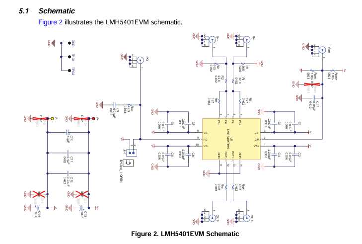
Using the LMH5401 for differential inputs is possible, however the on chip resistors will need to be changed first. The LMH5401 device has an internal resistance of 25 Ω between the output and the FB connections. Once the desired value of the Rf resistors is determined reduce them by 25 Ohms. To impedance match a 100-Ω differential source, the Ri- and R2 resistors both need to be 50 Ω. The desired gain will then determine the required value for Rf+ and Rf-. The gain will be Av = (Rf +25)/ Rg. As with other RF devices the final, system gain will depend on the source resistance and the load resistance.
4.5 Differential Outputs
The LMH5401EVM has two output SMA connectors that are designed to mate to 50-Ω test equipment. By connecting both outputs to 50-Ω test equipment, the output load is 100-Ω differential. With the on chip and on board matching resistors, the total load to the amplifier is 200 Ω. The matching resistors cause a 6-dB loss in voltage gain. The evaluation board has 40-Ω resistors on the board because there are 10-Ω output resistors on chip inside the device.
4.6 Single-Ended Outputs
Using an external balun to combine the two differential outputs creates a single-ended signal that can be interfaced to most 50-Ω test equipment. This is the method used by TI engineers to create the datasheet plots. To match the performance of the LMH5401 device, a very broadband balun must be selected. TI recommends the Marki B0100 or the PicoPulse Labs 5310A baluns.
5 LMH5401EVMSchematic,Layout,andBillofMaterials
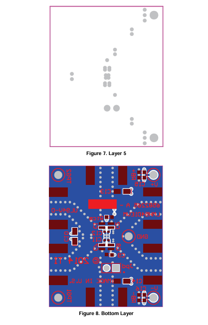
ThissectioncontainstheEVMschematic,PCBlayouts,andthebillofmaterials(BOM).
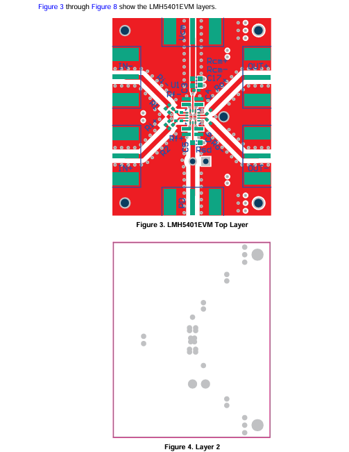
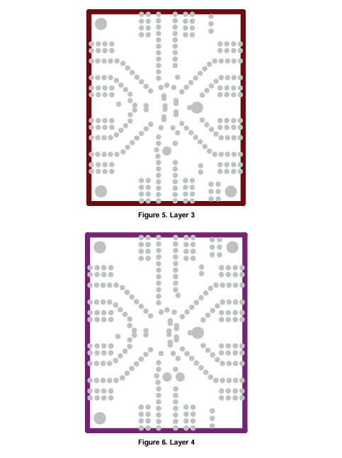
5.2 LMH5401EVM Layers
- LP8557IEVM_TI(德州仪器)中文资料_英文资料_价格_PDF手册
- LAUNCHXL-F28027F TI(德州仪器)中文资料_英文资料_价格_PDF手册
- DLPDLCR160CPEVM DLP160CP TI(德州仪器)中文资料_英文资料_价格_PDF手册
- THS4631DDAEVM TI(德州仪器)中文资料_英文资料_价格_PDF手册
- DAC3482EVM TI(德州仪器)中文资料_英文资料_价格_PDF手册
- THS4302EVM TI(德州仪器)中文资料_英文资料_价格_PDF手册
- ADS7038Q1EVM-PDK_TI(德州仪器)中文资料_英文资料_价格_PDF手册
- LM3450AEV230V30/NOPB_TI(德州仪器)中文资料_英文资料_价格_PDF手册
- TPS72728DSEEVM-406_TI(德州仪器)中文资料_英文资料_价格_PDF手册
- WL1835MODCOM8A_TI(德州仪器)中文资料_英文资料_价格_PDF手册
- TAS5424BQ1DKDEVM_TI(德州仪器)中文资料_英文资料_价格_PDF手册
- ADS7042EVM-PDK_TI(德州仪器)中文资料_英文资料_价格_PDF手册
- TMDS570LS31HDK_TI(德州仪器)中文资料_英文资料_价格_PDF手册
- VCA8500BOARD_TI(德州仪器)中文资料_英文资料_价格_PDF手册
- DEM-SOT223LDO_TI(德州仪器)中文资料_英文资料_价格_PDF手册
 工商网监
工商网监