
TPA3107D2EVM
1 Introduction
1.1 Description
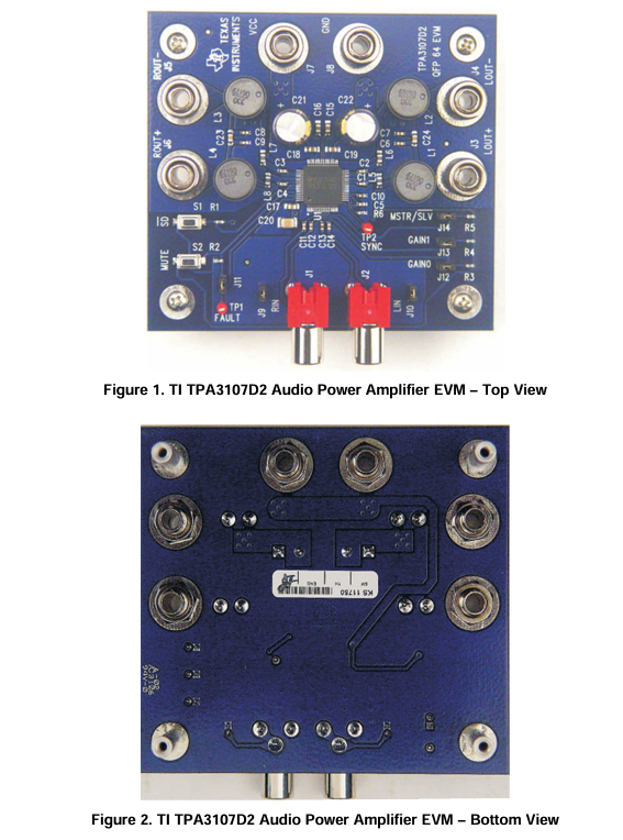
The TPA3107D2 evaluation module consists of a single 15-W/channel, class-D, stereo audio power
amplifier complete with a small number of external components mounted on a circuit board that can be
used to directly drive a speaker with an external analog audio source as the input
2
Operation
2.1 Quick Start List for Stand-Alone Operation
Follow these steps to use the TPA3107D2 EVM stand-alone or when connecting it into existing circuits or equipment. Connections to the EVM module can be made using banana plugs for the power supply and output connections. The inputs accept standard RCA plugs.
2.1.1 Power Supply
Ensure that all external power sources are set to OFF.
2. Connect an external regulated power supply adjusted from 10 V– 26 V to the module VCC (J7) and GND (J8) banana jacks taking care to observe marked polarity.
2.1.2 Evaluation Module Preparations
2.1.2.1 Inputs and Outputs
1. If connecting to a fully differential input or a grounded input (the shield of the RCA jack is GND),
remove jumpers J9 and J10 from the EVM board. These are located next to the input jacks J1 and J2. If connecting to a floating source, like a portable CD player, install J9 and J10. After setting the J9 and J10 jumpers appropriately, connect the audio source to J1 (RIGHT) and J2 (LEFT).
2. Connect a speaker across ROUT+ (J6) and ROUT- (J5). Connect another speaker across LOUT+ (J
and LOUT- (J4).
3. Install both gain jumpers GAIN0 (J12) and GAIN1 (J13). This sets the gain of the amplifier to the
lowest level, 20 dB.
4. Remove the jumper at MSTR/SLV (J14). If only one TPA3107D2 is evaluated, it must be configured as the master. If multiple EVMs are connected together using the SYNC output (TP2), the additional
EVMs must be configured in the slave mode by installing the J14 jumper.
5. Remove the jumper J11. This places the device in a latched mode when a short-circuit event occurs.
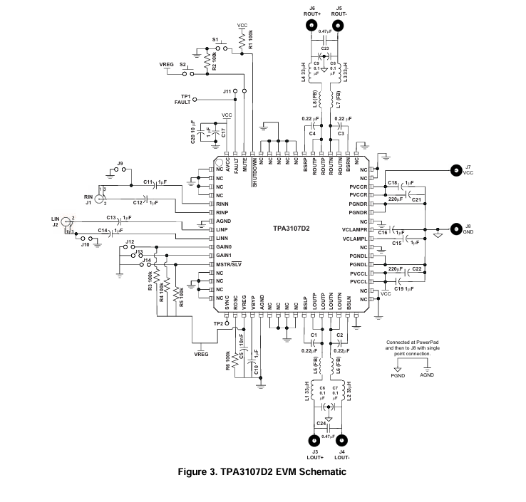
3 TPA3107D2EVMSchematic
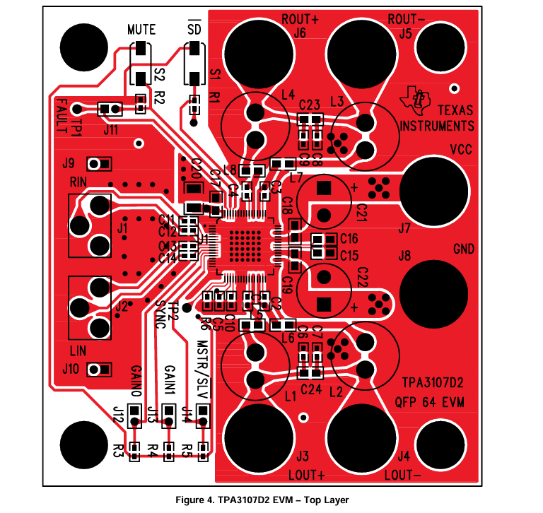
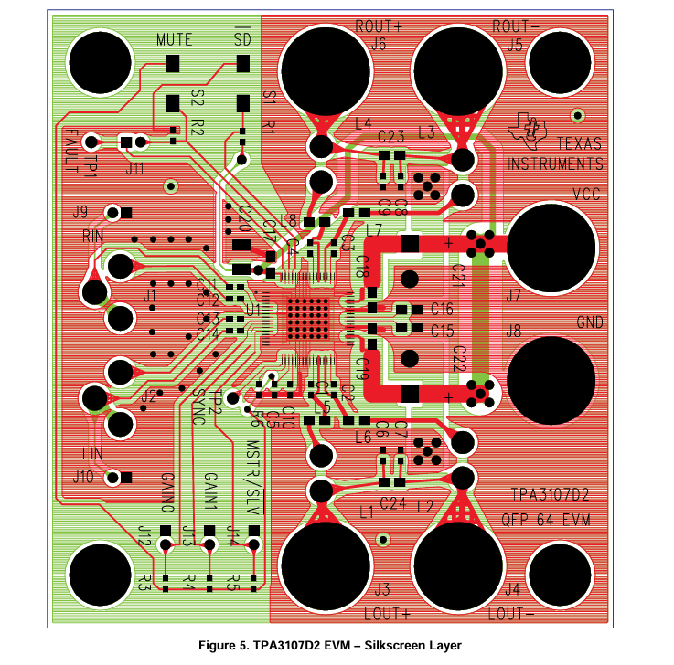
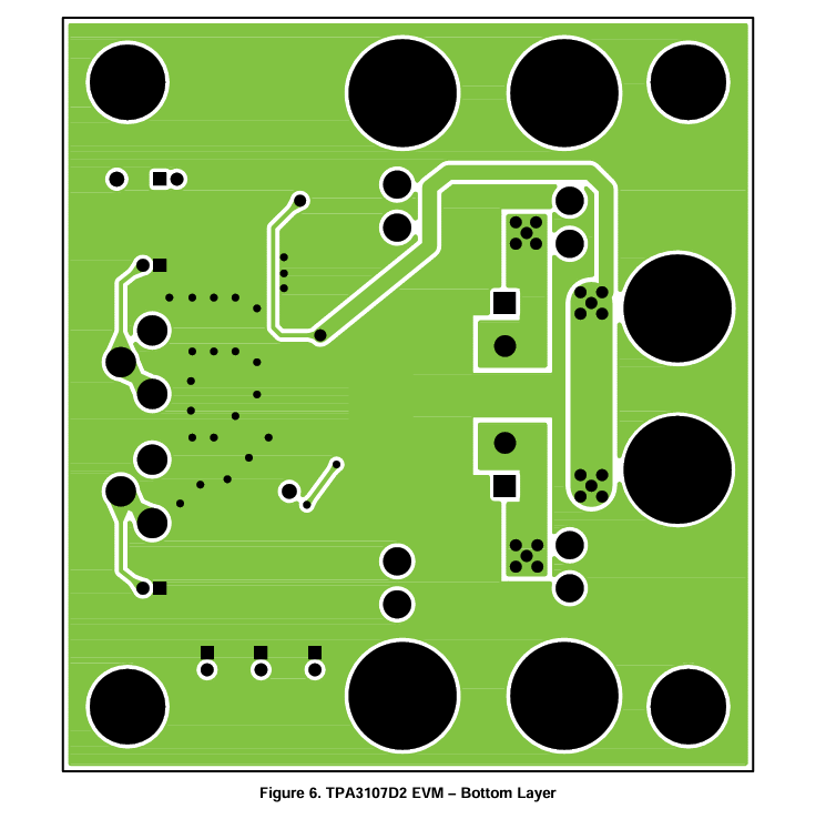
4 TPA3107D2 EVM PCB Layers
- LP8557IEVM_TI(德州仪器)中文资料_英文资料_价格_PDF手册
- LAUNCHXL-F28027F TI(德州仪器)中文资料_英文资料_价格_PDF手册
- DLPDLCR160CPEVM DLP160CP TI(德州仪器)中文资料_英文资料_价格_PDF手册
- THS4631DDAEVM TI(德州仪器)中文资料_英文资料_价格_PDF手册
- DAC3482EVM TI(德州仪器)中文资料_英文资料_价格_PDF手册
- THS4302EVM TI(德州仪器)中文资料_英文资料_价格_PDF手册
- ADS7038Q1EVM-PDK_TI(德州仪器)中文资料_英文资料_价格_PDF手册
- LM3450AEV230V30/NOPB_TI(德州仪器)中文资料_英文资料_价格_PDF手册
- TPS72728DSEEVM-406_TI(德州仪器)中文资料_英文资料_价格_PDF手册
- WL1835MODCOM8A_TI(德州仪器)中文资料_英文资料_价格_PDF手册
- TAS5424BQ1DKDEVM_TI(德州仪器)中文资料_英文资料_价格_PDF手册
- ADS7042EVM-PDK_TI(德州仪器)中文资料_英文资料_价格_PDF手册
- TMDS570LS31HDK_TI(德州仪器)中文资料_英文资料_价格_PDF手册
- VCA8500BOARD_TI(德州仪器)中文资料_英文资料_价格_PDF手册
- DEM-SOT223LDO_TI(德州仪器)中文资料_英文资料_价格_PDF手册
 工商网监
工商网监