
TPS7B6701EVM
TPS7B6701QPWPRQ1 高压 LDO EVM
The Texas Instruments TPS7B6701EVM evaluation module (EVM) helps designers evaluate the operation and performance of the TPS7B6701-Q1 linear regulator. The EVM contains one linear regulator (see Table 1).

1 Setup
This section describes the jumpers and connectors on the EVM as well and how to properly connect, set up, and use the TPS7B6701EVM.
1.1 Input/Output Connector Descriptions
TP_VIN —This input connector is the protected power input for the regulator. The test point provides a power (VIN) connection which powers the EVM.
J_EN —This jumper is a three-head jumper that enables and disables the device. Short pin 1 and pin 2 of J_EN to disable the device. Short pin 2 and pin 3 of J_EN to force the voltage at EN to equal the voltage at VIN.
TP_EN —This test point is a power test point which measures the voltage at EN. The user can also apply power to EN through this test point directly.
TP_GND —This connector is the ground return for the regulator. Three GND test points on the EVM allow the user to power the EVM, connect the load, and attach an oscilloscope ground lead.
TP_PG —This test point is a power test point that monitors the status of the PG pin.
J_DELAY —This jumper is a three head jumper that allows the user to select different capacitors
connected to the DELAY pin in order to vary the power-on reset delay-time.
TP_ADJ —This test point allows the user to measure the voltage of the ADJ pin.
TP_VOUT —This output connector is the power output for the regulator. The test point provides a
connection to attach a load to the EVM.
1.2 EVMSetup
The input voltage range for the tracker is 4 V to 40 V. The EVM can support up to 450-mA of load current.To set up the EVM, use the following steps:
1. Short pin 2 and pin 3 of J_EN.
2. Short pin 1 and pin 2 of J_DELAY.
3. Set the input voltage supply voltage to 12 V.
4. Set the current-limit to 1 A.
5. Connect the input power supply positive lead to VIN.
6. Connect the return lead to GND.
7. Apply the load between VOUT and GND.
1.3 Operation
The TPS7B6701 powers up after the VBAT voltage has exceeded the power-on reset threshold. The PCB offers footprints for the TPS7B6701-Q1 device.
2 Board Layout
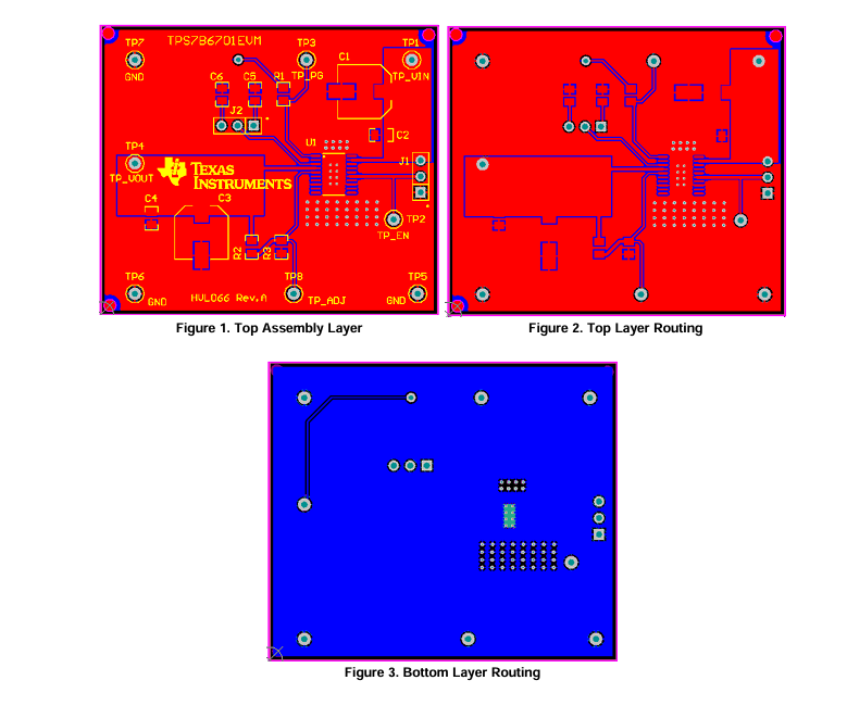
Figure 1, Figure 2, and Figure 3 show the board layout for the TPS7B6701EVM. The large quantities of via place close to the device footprint help to enhance thermal performance. The device pins must be soldered to the copper landing on the PCB for optimal performance. The PCB provides 2-oz copper planes on the top and bottom to dissipate heat.
3 SchematicandBillofMaterials
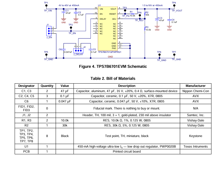
 Figure4showstheschematicof theTPS7B6701EVMandTable2liststhebillofmaterials.
- LP8557IEVM_TI(德州仪器)中文资料_英文资料_价格_PDF手册
- LAUNCHXL-F28027F TI(德州仪器)中文资料_英文资料_价格_PDF手册
- DLPDLCR160CPEVM DLP160CP TI(德州仪器)中文资料_英文资料_价格_PDF手册
- THS4631DDAEVM TI(德州仪器)中文资料_英文资料_价格_PDF手册
- DAC3482EVM TI(德州仪器)中文资料_英文资料_价格_PDF手册
- THS4302EVM TI(德州仪器)中文资料_英文资料_价格_PDF手册
- ADS7038Q1EVM-PDK_TI(德州仪器)中文资料_英文资料_价格_PDF手册
- LM3450AEV230V30/NOPB_TI(德州仪器)中文资料_英文资料_价格_PDF手册
- TPS72728DSEEVM-406_TI(德州仪器)中文资料_英文资料_价格_PDF手册
- WL1835MODCOM8A_TI(德州仪器)中文资料_英文资料_价格_PDF手册
- TAS5424BQ1DKDEVM_TI(德州仪器)中文资料_英文资料_价格_PDF手册
- ADS7042EVM-PDK_TI(德州仪器)中文资料_英文资料_价格_PDF手册
- TMDS570LS31HDK_TI(德州仪器)中文资料_英文资料_价格_PDF手册
- VCA8500BOARD_TI(德州仪器)中文资料_英文资料_价格_PDF手册
- DEM-SOT223LDO_TI(德州仪器)中文资料_英文资料_价格_PDF手册
 工商网监
工商网监