
TPA6021A4EVM
EVALUATION MODULE FOR TPA6021A4
Thischapter providesanoverviewof theTexas Instruments (TI) TPA6021A4audio amplifier evaluationmodule. It includes a list of EVM features, a brief illustrated descriptionof themodule,andalistofEVMspecifications
1 Introduction
1.1 FeatureHighlights
TheTITPA6021A4audioamplifierevaluationmoduleincludesthefollowingfeatures:
• TPA6021A4stereo2-Waudiopoweramplifierevaluationmodule
–Internaldepopcircuitrytominimizetransientsinoutputs
–Dualchannel,bridge-tiedload(BTL)orsingle-ended(SE)operation
–2Wperchanneloutputpower into4Ωat5V,BTL
–Lowcurrentconsumptioninshutdownmode(maximum20µA)
–DCvoltagevolumecontrol from20dBto–40dB,and–85dBmute(BTLMode)
–SEdcvoltagevolumecontrolproportional toBTLgainsetting
–PhenolicsinglesidedPCBboard–Differentialstereoinputs
–Afademodeslowlyrampsupordownthevolumewhencomingoutoforgoingintoshutdown.
1.2 Description
The TPA6021A4 stereo 2-W audio power amplifier evaluation module is a complete, 2-W per channel stereo audio power amplifier with dc volume control. It consists of the TI TPA6021A4 stereo 2-W audio power amplifier IC along with a small number of other parts mounted on a circuit board that measures approximately 2 1/4 inches by 1 1/2 inches (see Figure 1).
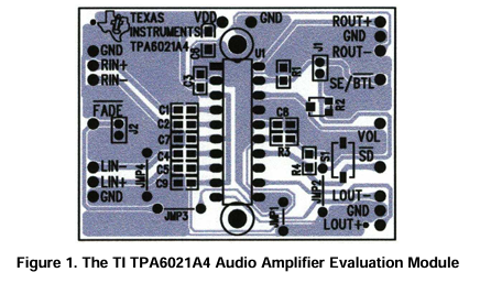
Two screw holes are located at the top and bottom of the IC to allow easy mounting of an external heatsink. Single in-line header pins extend from the underside of the module circuit board to allow the EVM to be plugged into the TI plug-n-play audio amplifier evaluation platform (slou011), or to be wired directly into existing circuits and equipment when used stand-alone.
1.3 Quick Start List for Stand-Alone
Follow these steps to use the TPA6021A4 EVM stand-alone or when connecting it into existing circuits or equipment. Refer to Figure 1 for pinouts and connections. Connections to the TPA6021A4 module header pins can be made via individual sockets, wire-wrapping, or soldering to the pins, either on the top or the bottom of the module circuit board.
• PowerSupply
1. Ensure that all external power sources are set to OFF.
2. Connect an external regulated power supply set to 5 V to the module VDD and GND pins taking
care to observe marked polarity.
• Inputs and Outputs
1. Ensure that audio signal source level adjustments are set to minimum.
2. Connect the right (left) positive lead of the audio source to the module RIN+ (LIN+) pins and the
negative lead to the RIN– (LIN–) pins. If using the headphone inputs, connect the positive audio
source to the module RIN+ (LIN+) and both the negative lead and GND to RIN– (LIN–). The inputs
can be used with a differential or single-ended audio source.
3. Select output mode:
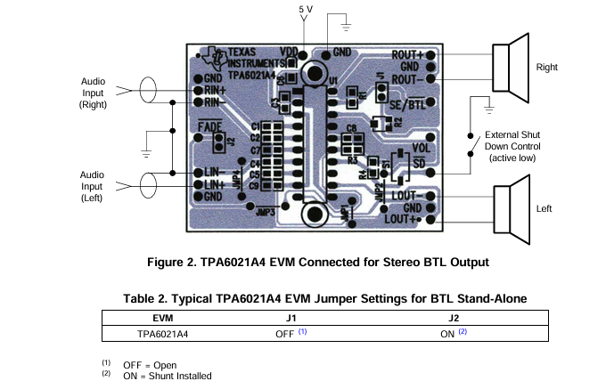
a. For BTL output, connect a speaker to the module OUT+ and OUT– pins of each channel (see
Figure 2),
or
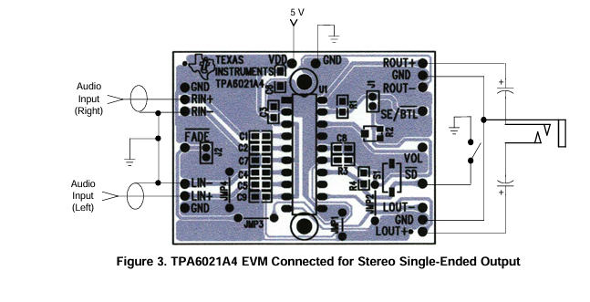
b. For single-ended output, connect a headphone or a speaker to the module OUT+ and GND
pins of each channel through a 33-µF to 1000-µF output-coupling capacitor (see Figure 3).
• Control Inputs
1. Connect control lines to the various module control input pins as needed:
a. SE/BTL: A high selects the single-ended (SE) output mode; a low or float selects the
bridge-tied load (BTL) output mode.
b. SD: A low shuts down the amplifier IC on the module; a high or float allows normal operation.
c. FADE: A low places the amplifier in FADE mode which slowly increases/decreases the gain
when leaving/entering the SHUTDOWN state; a high or float allows a quick ramp of gain when
entering/leaving SHUTDOWN.
• Power-Up
1. Verify correct voltage and input polarity and set the external power supply to ON.
The EVM should begin operation.
2. Adjust the signal source level as needed.
3. Adjust the BTL (speaker) volume as needed by turning the R2 potentiometer in the clockwise
direction to increase the volume. Turn in the counter clockwise direction to decrease the volume.
The VOL pin on the right side of the EVM is provided to monitor the dc voltage.
1.4 TPA6021A4EVMConnectedforBTLOutputandHeadphoneInput
1.5 TPA6021A4EVMConnectedforSingle-EndedOutputandHeadphoneInput
2
Reference
ON =Shunt Installed
ON (1)
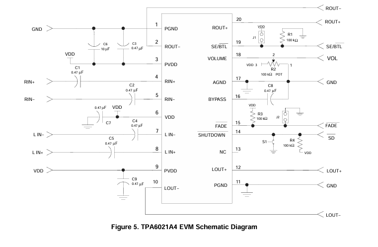
The TPA6021A4 EVM board layers, board schematic, and parts list are presented in this chapter.
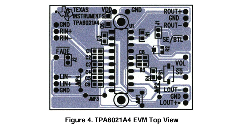
2.1 TPA6021A4 EVM Layers and Board Schematic
2 Reference
The TPA6021A4 EVM board layers, board schematic, and parts list are presented in this chapter.
2.1 TPA6021A4 EVM Layers and Board Schematic
- LP8557IEVM_TI(德州仪器)中文资料_英文资料_价格_PDF手册
- LAUNCHXL-F28027F TI(德州仪器)中文资料_英文资料_价格_PDF手册
- DLPDLCR160CPEVM DLP160CP TI(德州仪器)中文资料_英文资料_价格_PDF手册
- THS4631DDAEVM TI(德州仪器)中文资料_英文资料_价格_PDF手册
- DAC3482EVM TI(德州仪器)中文资料_英文资料_价格_PDF手册
- THS4302EVM TI(德州仪器)中文资料_英文资料_价格_PDF手册
- ADS7038Q1EVM-PDK_TI(德州仪器)中文资料_英文资料_价格_PDF手册
- LM3450AEV230V30/NOPB_TI(德州仪器)中文资料_英文资料_价格_PDF手册
- TPS72728DSEEVM-406_TI(德州仪器)中文资料_英文资料_价格_PDF手册
- WL1835MODCOM8A_TI(德州仪器)中文资料_英文资料_价格_PDF手册
- TAS5424BQ1DKDEVM_TI(德州仪器)中文资料_英文资料_价格_PDF手册
- ADS7042EVM-PDK_TI(德州仪器)中文资料_英文资料_价格_PDF手册
- TMDS570LS31HDK_TI(德州仪器)中文资料_英文资料_价格_PDF手册
- VCA8500BOARD_TI(德州仪器)中文资料_英文资料_价格_PDF手册
- DEM-SOT223LDO_TI(德州仪器)中文资料_英文资料_价格_PDF手册
 工商网监
工商网监