OPT3101EVM
EVAL BOARD FOR OPT3101
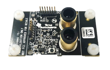
This user’s guide provides an overview of the OPT3101 time-of-flight (ToF) proximity sensor evaluation module (EVM). The OPT3101EVM is a single-pixel implementation of the OPT3101 device consisting of a printed-circuit board (PCB) and an accompanying software package. The EVM is intended for prototyping and evaluation. This user’s guide includes an overview of the EVM hardware and software in addition to the schematic diagram, layout, and bill of materials. Throughout this document, the abbreviation EVM and the term evaluation module are synonymous with the OPT3101EVM.
2 Introduction
OPT3101 device is a high-speed, high-resolution AFE for continuous wave, time-of-flight (ToF) based proximity sensing, and range finding. The purpose of the OPT3101EVM is to expedite evaluation and system development of the OPT3101. The evaluation kit consists of a printed-circuit board (PCB), available for purchase on the OPT3101EVM page, and a software package called Latte, which is available for download on the OPT3101EVM page under software. The PCB is a single-pixel system that uses the OPT3101 device for ToF proximity sensing. The PCB connects to a computer running the Latte software through USB. The Latte software allows visualization and logging of the OPT3101 readings, setting different modes of operation, reading and writing of register settings on the device, and the creation of custom Python® scripts.

The following sections are divided into hardware, software installation, using the EVM, and troubleshooting. The last section at the end of this guide includes the EVM schematic, layout, and bill of materials (BOM). The OPT3101EVM Hardware section gives an overview of the OPT3101EVM PCB, covering the different components of the board and outlining the functions of each. The Section 4 section provides the steps needed to install and launch the Latte software package. The Using the EVM section describes how to use the Latte software to take readings on the EVM
3 OPT3101EVM Hardware
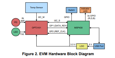
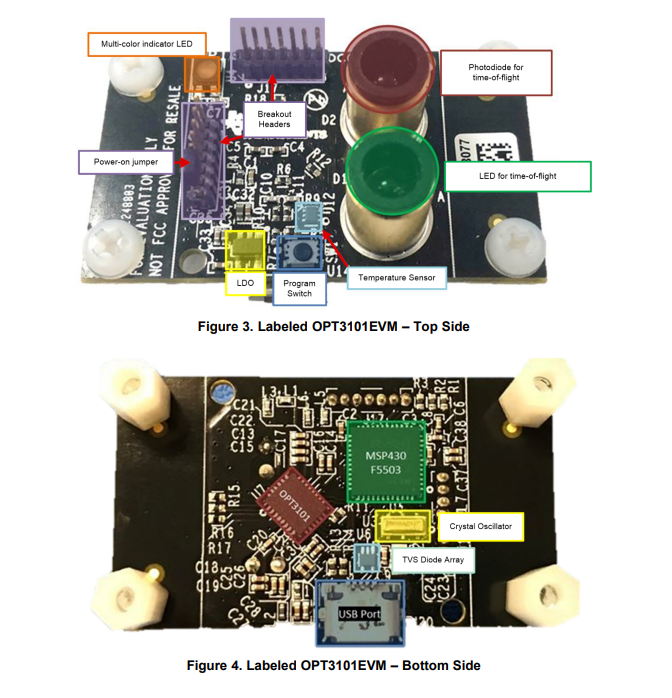
shows the hardware block diagram for the OPT3101EVM. The block diagram includes all major components on the PCB and shows how they are connected. The direction of the arrow shows the flow of information between the components. Figure 3 and Figure 4 show the physical location of these components on the PCB. The following subsections describe each component in detail.

3.1 MSP430 Microcontroller
The MSP430F5503 has a USB interface, allowing connection to a PC, and acts as a communication bridge between the OPT3101 and the PC. The MSP430 microcontroller is loaded with C++ firmware for interfacing with the OPT3101 over I 2C, in addition to the other components on the PCB. The MSP430 also has a calibration configuration for the board stored in onboard flash storage.
The MSP430 registers 2 USB COM ports with the PC it is plugged in to. The OPT3101 Control Port is used for sending control commands to the MSP430. This includes reading and writing registers on the OPT3101 and interfacing with the MSP430 flash storage. The OPT3101 Data Port is used only for streaming data from the EVM to the PC. This allows for maximum data rates when receiving real-time data from the OPT3101 during high-speed capture.
3.2 I 2C Buses and Temperature Sensor
The OPT3101 has two I 2C buses. On the main I 2C bus, labeled I2C_S, the OPT3101 is a slave device. This bus is used to control the OPT3101 and read data by reading and writing registers on the device. The OPT3101 also has a secondary I 2C bus, I2C_M, for which it is the master. This bus allows an external temperature sensor and an EEPROM to be controlled by the OPT3101. The OPT3101 contains an internal temperature sensor, which is used for temperature calibration. This sensor has 8-bit integer resolution. Adding an external temperature sensor, such as that used on the EVM, allows up to 12 bits of resolution to be obtained with one sign bit, 7 integer bits, and 4 fractional bits. This allows for more accurate temperature correction. An external EEPROM allows for an OPT3101 register configuration to be stored and loaded on power-up. This means that the device does not need an I 2C master to configure it on power-up. On the EVM, only a temperature sensor is used on this bus.

3.3 Light-Emitting Diode (LED) and Photodiode (PD) for ToF Measurements
As the introduction states, this EVM is a single-pixel system. There is a single LED-photodiode pair that connects to the OPT3101 and is used for ToF measurements. The EVM uses a 850-nm centroid (860-nm peak) wavelength IR LED (SFH 4550), and a 900-nm peak sensitivity IR photodiode (SFH 213 FA).
Electroless nickel immersion gold (ENIG)cylinders on the EVM encircle both the LED and photodiode. The cylinders provide both optical and electrical shielding between the LED and photodiode, this reduces crosstalk.
3.4 Headers and Power-On Jumper
The headers break out a number of signals from the EVM for debug and to provide more flexibility in the ways the EVM can be used. Figure 6 shows how to power the board by placing the power-on jumper on the bottom two pins of J19. This connects the 3.3-V output of the LDO to the rest of the components on the EVM. Figure 5 and Figure 6 show the complete list of signals that are broken out to the headers.

- CC2340R52E0RKPR_TI(德州仪器)中文资料_英文资料_价格_PDF手册
- MSP430FR2355TPTR_TI(德州仪器)中文资料_英文资料_价格_PDF手册
- MSP430G2453IPW20R_TI(德州仪器)中文资料_英文资料_价格_PDF手册
- CD74AC04M96_TI(德州仪器)中文资料_英文资料_价格_PDF手册
- LP-MSPM0G3507_TI(德州仪器)中文资料_英文资料_价格_PDF手册
- TPA6130A2YZHR_TI(德州仪器)中文资料_英文资料_价格_PDF手册
- 081C021CIMKX/NOPB_TI(德州仪器)中文资料_英文资料_价格_PDF手册
- ISO7760QDWQ_TI(德州仪器)中文资料_英文资料_价格_PDF手册
- ISOW7821DWER_TI(德州仪器)中文资料_英文资料_价格_PDF手册
- ISO6760FDWR_TI(德州仪器)中文资料_英文资料_价格_PDF手册
- ADS7054IRUGR_TI(德州仪器)中文资料_英文资料_价格_PDF手册
- ADC12QJ1600ALRSHP_TI(德州仪器)中文资料_英文资料_价格_PDF手册
- AM26C32IDR_TI(德州仪器)中文资料_英文资料_价格_PDF手册
- ISO6721FQDWVRQ1 _TI(德州仪器)中文资料_英文资料_价格_PDF手册
- LOG114EVM_TI(德州仪器)中文资料_英文资料_价格_PDF手册
